
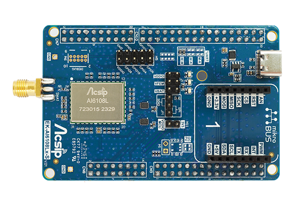


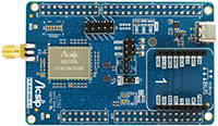
EK-AI6108L-S is an evaluation board mounted the AI6108L transceiver module of Morse Micro solution which is a complete Wi-Fi HaLow connectivity solution provides for users in developing their application.
There is a MM6108 inside the module and each of which incorporates the Radio, PHY, and MAC sections designed in accordance with the IEEE 802.11ah standard, supporting data rates up to 32.5 Mbps (@BW=8MHz).
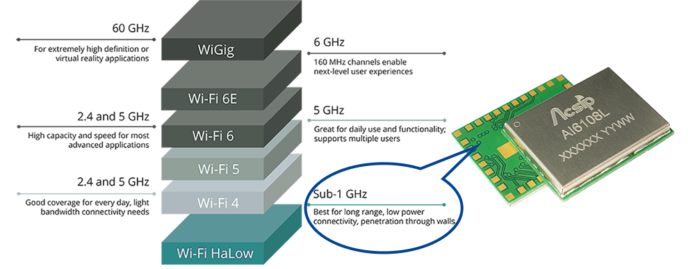
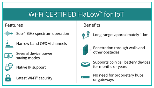
The standard provides for operation in the sub-1 GHz license-exempt RF bands.
The module supports programmable operation in these bands, worldwide, between 902 MHz and 928MHz.
And his module has been designed to provide a simplified Wi-Fi HaLow connection to external hosts, while leveraging the latest WPA3 security protocol.
It includes an ultra-long-reach PA, high linearity LNA, T/R switch, and 32 MHz crystal oscillator, making it an ideal choice for customers looking to replace their existing RF technology with Wi-Fi HaLow.
Developer could refer to below link for product specification for detail in studying.
.png)
| AI6108L | 1/2/4/8 MHz | 902~928 MHz | 21 dBm | *FCC |
| AI6108LT | 1/2/4 MHz | 922~928 MHz | 9 dBm | TELEC |
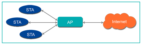
User could develop such solution with host platform to implement application on STA/AP relevant examples based on SDK/HDK resources.
For example, there is description about preparation of implement steps.
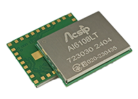
1) EK-AI6108LT-S could be mounted on STM32 UNCLEO-U575ZI-Q be a host and simulates a Wi-Fi HaLow STA role played.
♦ This uses the STM32 NUCLEO-U575ZI-Q as the host MCU development board.
♦ The two boards connect together as shown in the photo below. This is connected to the PC by the micro-USB connector CN1 on the Nucleo, as highlighted below. This will provide power and debug connectivity to the platform.
.png)
♦ Optionally power can be supplied via the USB-C connector on the EK-AI6108Lx-S instead. In most cases this should not be necessary, but may be necessary if the USB port is not able to supply sufficient power. Note that if power is supplied via the USB-C connector then JP6 on the Nucleo must be removed. The Nucleo must still be connected to the PC via micro-USB connector CN1 in order to use the debug interface.
2) User could refer to SDK provided by Acsip to select suitable examples as reference in software developing.
♦ IoT - STM32/ESP32 platform with RTOS
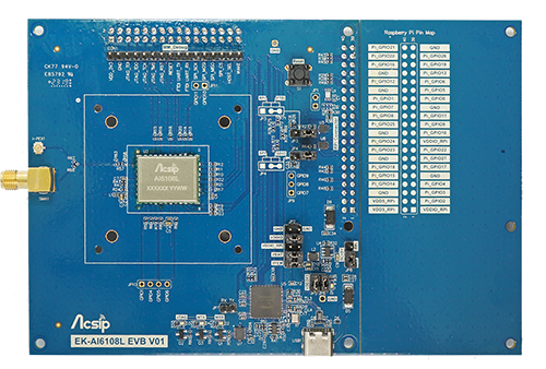
♦ Linux - Kernel 5.1.0 above supported (Raspberry Pi)
3) RF performance and behaviors verify test could be evaluated by this EVK or the EVK dedicated on wireless certification test to be compliant with local regulation. For further inquiring, you could check sales@acsip.com.tw as well.
After research and development of the Wi-Fi HaLow product, user could refer to official website or local LAB for certification service and information, there is a reference in Wi-Fi CERTIFIED HaLowTM.
Related Resource
| ⇒ | ||
| ⇒ | ||
| ⇒ | ||
| ⇒ | ||
| ⇒ |
Related Products
 |
AI6108LIEEE802.11 ah Transceiver |
 |
EK-AI6108L-S KITIEEE802.11 ah Transceiver |
 |
AI6108LTIEEE802.11 ah Transceiver |
 |
EK-AI6108LT-S KITIEEE802.11 ah Transceiver |
.png "AI7933CLD") |
AI7933CLDARM Cortex-M33 MCU + Wi-Fi 802.11 a/b/g/n/ac/ax + BLE 5.0 + HiFi4 DSP |
.png "EK-AI7933CLD KIT") |
EK-AI7933CLD KITWiFi6 2.4/5G + BT 5 + HiFi4 DSP |
.png "AI7931LD") |
AI7931LDARM Cortex-M33 MCU + Wi-Fi 802.11 a/b/g/n/ac/ax + BLE 5.0 |
.png "EK-AI7931LD KIT") |
EK-AI7931LD KITWiFi6 2.4/5G + BT 5 |
 |
AI7697HDARM Cortex-M4 MCU + Wi-Fi 802.11 a/b/g/n + BT 4.2 |
 |
EK-AI7697HDXBWiFi4 2.4/5G + BT 4.2 |
 |
AI7688H580 MHz MIPS CPU module + Wi-Fi b/g/n + Ethernet 1-port |
 |
EK-AI7688HWiFi4 + Ethernet |

For more information, or for sales inquiries, please contact AcSiP Technology Corp
General Description
The EK-AI6108L-S Kit mounded AI6108L module for developer to estimate Wi-Fi HaLow in STA/AP functions validation, features simulation and applications integrated peripherals.
The module has designed in compliance with the IEEE 802.11ah standard, supporting data rates up to 32.5 Mbps (@BW=8MHz) with programmable operation between 902 MHz and 928 MHz .
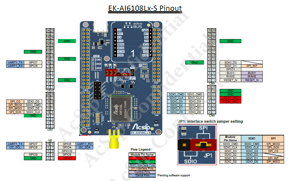
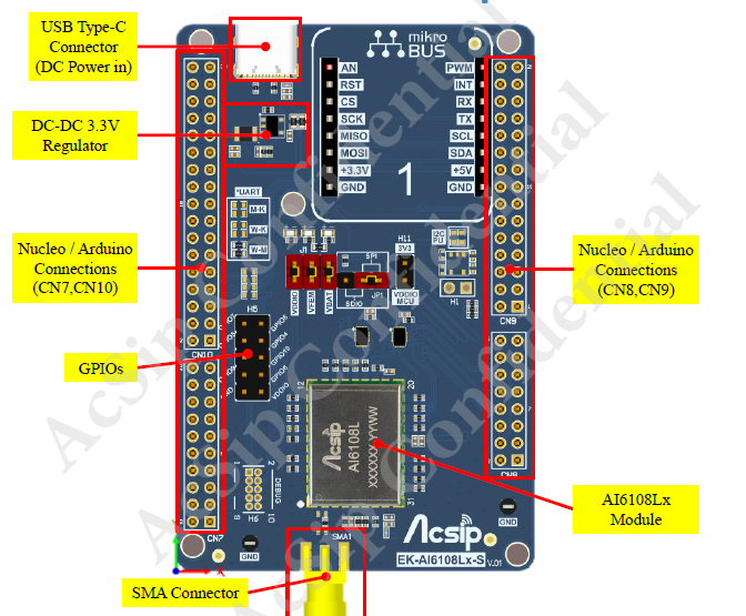
Evaluation Board Pinout
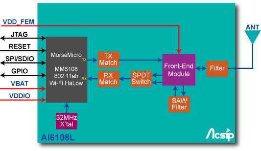
Module Block diagram
This module has been designed to provide a simplified Wi-Fi HaLow connection to external hosts, while leveraging the latest WPA3 security protocol. It includes an ultra-long-reach PA, high linearity LNA, T/R switch, and 32 MHz crystal oscillator, making it an ideal choice for customers looking to replace their existing RF technology with Wi-Fi HaLow.
For detail reference, user could get datasheet for further study to bring up this solution from host side based on suitable packages of SDK and start SW implement in CLI of engineering, normal mode in the beginning. Then user could keep developing application with Wi-Fi HaLow connectivity to join this new ecosystem.
Functional Description
Reference Platform as host in SW developing by STA role played
There are essential steps for referring in HDK, SDK setup.
1) User need find a Host (MCU/MPU/CPU) to drive AI6108LT as wireless connectivity of Wi-Fi HaLow.
♦ STM32 NUCLEO-U575ZI-Q be a host MCU after this board-to-board connection
♦ The two boards connect together as shown in the photo below. This is connected to the PC by the micro-USB connector CN1 on the Nucleo, as highlighted below. This will provide power and debug connectivity to the platform.
♦ Optionally power can be supplied via the USB-C connector on the EK-AI6108Lx-S instead. In most cases this should not be necessary, but may be necessary if the USB port is not able to supply sufficient power. Note that if power is supplied via the USB-C connector then JP6 on the Nucleo must be removed. The Nucleo must still be connected to the PC via micro-USB connector CN1 in order to use the debug interface.
2) According to selected host board platform, user could select suitable package of SDK to build example first. For above combination, you could apply for this example SDK from AcSiP sales team for this preparation of SW resource.
Studying this SDK and build out image for programming into host platform for sure. Then you could verify what function or behavior this example shown by log or other indicator of LED.
Related Resource
| ⇒ | ||
| ⇒ | ||
| ⇒ | ||
| ⇒ | ||
| ⇒ |
Related Products
|
AI6108LIEEE802.11 ah Transceiver |
|
EK-AI6108L-S KITIEEE802.11 ah Transceiver |
|
AI6108LTIEEE802.11 ah Transceiver |
|
EK-AI6108LT-S KITIEEE802.11 ah Transceiver |
|
AI7933CLDARM Cortex-M33 MCU + Wi-Fi 802.11 a/b/g/n/ac/ax + BLE 5.0 + HiFi4 DSP |
|
EK-AI7933CLD KITWiFi6 2.4/5G + BT 5 + HiFi4 DSP |
|
AI7931LDARM Cortex-M33 MCU + Wi-Fi 802.11 a/b/g/n/ac/ax + BLE 5.0 |
|
EK-AI7931LD KITWiFi6 2.4/5G + BT 5 |
|
AI7697HDARM Cortex-M4 MCU + Wi-Fi 802.11 a/b/g/n + BT 4.2 |
|
EK-AI7697HDXBWiFi4 2.4/5G + BT 4.2 |
|
AI7688H580 MHz MIPS CPU module + Wi-Fi b/g/n + Ethernet 1-port |
|
EK-AI7688HWiFi4 + Ethernet |
For more information, or for sales inquiries, please contact AcSiP Technology Corp.
General Description
.png) |
The EK-AI6108L-S board provides an affordable way for user to try his LPWAN IoT applications or new concepts evaluation. It also integrated connectors support STM32, Raspberry Pi boards (platform) with example from packages of SDK to evaluate connectivity of Wi-Fi HaLow solution in Long Range / High Data rate features. User can use SDK included examples to evaluate this feature then engage this connectivity to application targeted long range with higher data rate demand in deployment. |
Host Platform of STM32 series for STA developing
The SDIO data and command lines should be pulled up with 10k-100k resistors as per the SDIO 2.0 specification.
STM32WB55
♦ The two boards connect together as shown in the photo below. This is connected to the PC by the micro-USB connector CN15 on the Nucleo, as highlighted below. This will provide power and debug connectivity to the platform.
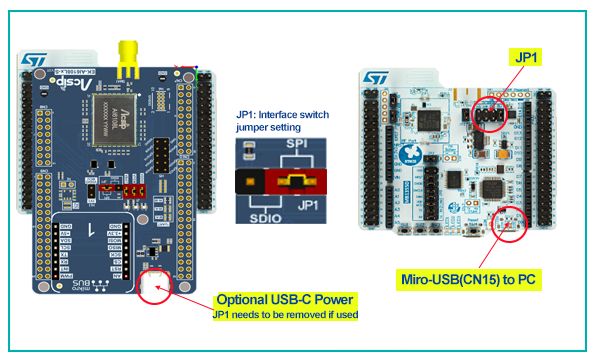
♦ Optionally power can be supplied via the USB-C connector on the EK-AI6108Lx-S instead. In most cases this should not be necessary, but may be necessary if the USB port is not able to supply sufficient power. Note that if power is supplied via the USB-C connector then JP1 on the Nucleo must be removed. The Nucleo must still be connected to the PC via micro-USB connector CN15 in order to use the debug interface.
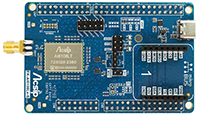
STM32U5
♦ The two boards connect together as shown in the photo below. This is connected to the PC by the micro-USB connector CN1 on the Nucleo, as highlighted below. This will provide power and debug connectivity to the platform.
♦ Optionally power can be supplied via the USB-C connector on the EK-AI6108Lx-S instead. In most cases this should not be necessary, but may be necessary if the USB port is not able to supply sufficient power. Note that if power is supplied via the USB-C connector then JP6 on the Nucleo must be removed. The Nucleo must still be connected to the PC via micro-USB connector CN1 in order to use the debug interface.
STM32F4
♦ The two boards connect together as shown in the photo below. This is connected to the PC by the micro-USB connector CN1 on the Nucleo, as highlighted below. This will provide power and debug connectivity to the platform.
.png)
♦ Optionally power can be supplied via the USB-C connector on the EK-AI6108Lx-S instead. In most cases this should not be necessary, but may be necessary if the USB port is not able to supply sufficient power. Note that if power is supplied via the USB-C connector then JP3 on the Nucleo must be removed. The Nucleo must still be connected to the PC via micro-USB connector CN1 in order to use the debug interface.
Host Platform with Linux for AP developing
.png)
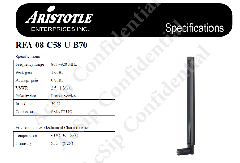
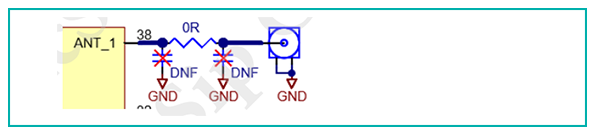
Antenna Selection
RF layout Notice
Suggest reserving 'PI' matching circuit between module and Antenna.
♦ For 'PI' matching components (L/C/R), use components that are sized close to the nominal trace width. e.g., for 10mil RF traces, use 0402 components, for 5mil trace width (on very thin PCB's) use 0201 components. Try to avoid larger 0603 or 0805 parts as they have larger parasitic capacitance and create impredance mismatches.
♦ Per others of Layout guide, user could refer to 'Applicatoin Note' for reminding in design.
⇒ Power Trace
⇒ Groud
⇒ RF Trace
Operation Instruction
♦ Preparing your host and connect to this board by control interface : SDIO/SPI
♦ Bring up evaluation board and connecting initial, state log from UART
♦ Power on Wi-Fi HaLow AP & have an essential check about Configuration(Freq./Region)
♦ Setup connection with AP
♦ Verify your connection performance – Ping, iPerf…
♦ Developing App integrated wireless connectivity by Wi-Fi HaLow
For further reference in AI6108L design, please check data pool for resource download or check sales rep for such info obtain as well.
Related Resource
| ⇒ | ||
| ⇒ | ||
| ⇒ | ||
| ⇒ | ||
| ⇒ |
Related Products
|
AI6108LIEEE802.11 ah Transceiver |
|
EK-AI6108L-S KITIEEE802.11 ah Transceiver |
|
AI6108LTIEEE802.11 ah Transceiver |
|
EK-AI6108LT-S KITIEEE802.11 ah Transceiver |
|
AI7933CLDARM Cortex-M33 MCU + Wi-Fi 802.11 a/b/g/n/ac/ax + BLE 5.0 + HiFi4 DSP |
|
EK-AI7933CLD KITWiFi6 2.4/5G + BT 5 + HiFi4 DSP |
|
AI7931LDARM Cortex-M33 MCU + Wi-Fi 802.11 a/b/g/n/ac/ax + BLE 5.0 |
|
EK-AI7931LD KITWiFi6 2.4/5G + BT 5 |
|
AI7697HDARM Cortex-M4 MCU + Wi-Fi 802.11 a/b/g/n + BT 4.2 |
|
EK-AI7697HDXBWiFi4 2.4/5G + BT 4.2 |
|
AI7688H580 MHz MIPS CPU module + Wi-Fi b/g/n + Ethernet 1-port |
|
EK-AI7688HWiFi4 + Ethernet |
For more information, or for sales inquiries, please contact AcSiP Technology Corp.
| Item | Description | Download Link |
|---|---|---|
| AI6108L Product Brief | AI6108L_Brief_Ver.01.pdf | Free |
| AI6108L Product Spec. (Datasheet) | AI6108L_SPEC_Ver.B.pdf | LoginContact Us |
| AI6108L Application Note | AI6108L_Application Note_Ver.A.pdf | LoginContact Us |
| EK-AI6108L-S User Guide | EK-AI6108L-S User Guide Ver.A.pdf | Free |
| Footprint | AI6108Lx Footprint.7z | LoginContact Us |
| Item | Description | Download Link |
|---|